
How to Export Drone Data to AutoCAD as Usable Linework

A drone image isn’t usable AutoCAD linework until it’s processed, referenced and converted into the right CAD format. To understand how to export drone data to AutoCAD, a professional first plans the capture around the required output, processes the imagery into a photogrammetric product, then uses ground control and CAD alignment to prepare vector linework, often as a DXF.

It’s understandable to expect a direct export from the drone, but the quality of the drawing depends on the steps between capture and CAD. The imagery may also produce a georeferenced GeoTIFF, elevation data, a point cloud or a 3D mesh, depending on the project. This article explains how those outputs are created, how imagery and ground control inform AutoCAD linework, and why a raster may need adjustment to align with a DXF in AutoCAD. You’ll also learn what affects the result and when professional processing can make the handover more reliable.

Key Takeaways

  • Define the intended CAD deliverable before capture, since the required output shapes the flight plan and image collection.
  • Understand how one imagery dataset can support different mapping and modelling outputs, from orthomosaics to point clouds and meshes.
  • See how ground control, georeferencing and careful raster alignment affect the accuracy of CAD linework.
  • Follow the professional workflow from image processing through export and final checks, so the handover suits the project’s needs.

Photogrammetric data for mapping and modelling software

For UK land, construction and boundary work, agree the intended use, coordinate reference system and accuracy requirements with the project surveyor. Drone imagery records visible conditions, but a traced line alone does not establish a legal boundary.

  1. Choose the required surface model. A digital terrain model represents the ground surface, while a digital surface model includes visible features such as roofs and vegetation. On a construction site, a terrain model may support ground assessment; a surface model can show structures and other raised features. Specify the measurements needed before processing.
  2. Request an orthophoto for plan-based work. An orthophoto corrects image perspective to create a consistent aerial view for mapping. A georeferenced GeoTIFF preserves scale and spatial reference information, making it useful for site and land surveys, roof plans and elevation drawings. That information helps place the image within a mapping workflow.
  3. Match the output to the task. Use an orthophoto as a visual base for tracing visible features, such as roof edges or access routes. Use a terrain or surface model when the task depends on elevation. Measurements from any output depend on processing, ground control and alignment, so let the project specification determine which measurements are suitable.
  4. Organise 3D models and project layers. A photogrammetric model adds depth to the mapped site, helping teams inspect building form and existing conditions. Keep the orthophoto, elevation models, point cloud and CAD linework as distinct, clearly named layers or files. During upload into mapping or modelling software, retain coordinate information and record each output’s purpose for later review.

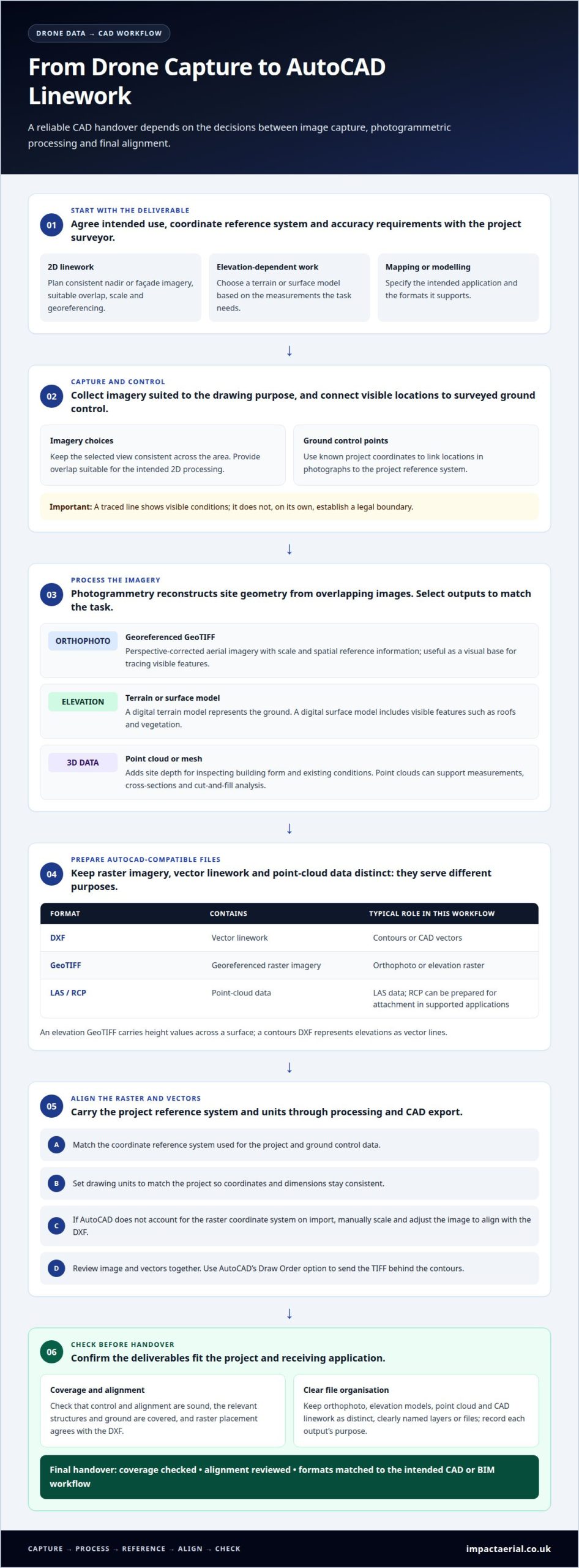
For 2D CAD outputs, capture should prioritise consistent nadir or façade imagery, proper overlap for 2D processing, and accurate scaling and georeferencing. Set the capture plan around the drawing purpose, and keep the selected view consistent across the area being documented. Confirm that overlap is suitable for the intended 2D processing, and carry the scale and georeferencing requirements through to the output. These priorities help align the CAD deliverable with the imagery, rather than treating image capture and drawing preparation as separate decisions. Record the capture choices with the project outputs so they can be reviewed alongside the resulting linework.

Processing imagery into orthomosaics, elevation mosaics, point clouds and meshes

  1. Select the processing workflow and deliverables. Photogrammetry software reconstructs site geometry from overlapping images, producing orthomosaics, elevation mosaics, point clouds or meshes. Outputs should match the task, with coverage and alignment checked before export. Mapping platforms can create AutoCAD-compatible DXF vectors and GeoTIFF imagery, which serve different purposes: DXF contains linework, GeoTIFF contains georeferenced raster imagery, and LAS contains point-cloud data.
  2. Prepare raster and contour outputs for CAD. An elevation GeoTIFF represents height values across a surface; a contours DXF represents those elevations as vector lines. AutoCAD may not account for a raster’s coordinate system when importing it, so scale and adjust the image manually to align with the DXF. Review the image and vectors together, then send the TIFF behind the contours using AutoCAD’s Draw Order option.
  3. Package point clouds for the receiving application. LAS files support drone-generated point clouds and 3D modelling workflows. Providers can prepare an RCP point cloud for attachment in AutoCAD, Revit or Civil 3D, subject to the receiving application’s supported formats. In AutoCAD, an RCP file is attached from the Insert tab’s Point Cloud section. Civil 3D or another product isn’t automatically required; the deciding factor is whether the chosen application supports the delivered format and intended workflow.
  4. Use the cloud to analyse existing conditions. A classified point cloud can support distance and volume measurements, cross-sections, cut-and-fill analysis and existing-condition models. Design teams can also compare proposed design intent with captured site conditions. Before delivery, check that the cloud covers the relevant structures and ground.
  5. Resolve alignment and export issues before handover. Coordinate mismatches, incomplete coverage or unsuitable formats can disrupt CAD use. The provider checks control and alignment, then corrects raster placement against the DXF. For commercial property survey data, specify the intended CAD or BIM workflow so deliverables match the project.
How to Export Drone Data to AutoCAD as Usable Linework

Converting drone imagery and ground control data into AutoCAD linework

  1. Set the project coordinate reference system and units. Understanding how to export drone data to AutoCAD starts with matching the project coordinate reference system to the ground control data. Apply the same reference during photogrammetric processing and CAD export. Drawing units must also match the project, such as metres for site measurements, so coordinates and dimensions stay consistent.
  2. Connect imagery to surveyed ground control. Ground control points link visible locations in drone photographs to known project coordinates. Incorporate them during processing, then assess how well the resulting model fits those points. Required accuracy depends on the survey’s intended use and deliverable; a single accuracy figure does not suit every AutoCAD project.
  3. Prepare and align the georeferenced image. Process the photographs into an orthophoto, then export a georeferenced GeoTIFF when a raster base is needed. AutoCAD may not account for the raster’s coordinate system on import, so scale and adjust it manually against the DXF linework. Project references and control points guide the alignment.
  4. Trace relevant features as CAD vectors. Use the aligned image as a visual reference to digitise agreed details, such as roof outlines, visible site edges or access routes, into a DXF. Named layers help CAD users distinguish features. A sound process for how to export drone data to AutoCAD also distinguishes visible image features from legal boundary determinations: tracing alone does not establish a boundary.
  5. Check the drawing against its source data. Overlay the DXF with the orthophoto and review control-point fit, units, coordinate placement and gaps. In AutoCAD, selecting a contour line displays its assigned Elevation in Properties. Before saving or handing over the drawing, check that the linework represents the agreed features.

A georeferenced GeoTIFF provides a raster image base, while a DXF contains digitised CAD vectors on named layers.

Drone imagery can be processed into 2D maps or 3D models, and one dataset may be used to generate both outputs. In a project that needs CAD linework, these options provide different ways to represent the same captured material. The choice between them can be made alongside the intended form of the final project output.

Export Drone Survey Data to AutoCAD Step-by-Step

  1. Confirm the CAD deliverable. Confirm which features and outputs the project needs before exporting. A site plan may require DXF linework and a georeferenced GeoTIFF, while a modelling workflow may need a point cloud. Use the agreed coordinate reference system and drawing units to guide processing and export settings.
  2. Process the imagery. Photogrammetry software aligns the photographs and ground control data to create the selected outputs. The professional reviews image coverage, model alignment and visible gaps before preparing CAD files. Where both a raster and vectors are required, the orthomosaic and linework need consistent spatial referencing.
  3. Digitise the requested features. The professional traces agreed details, such as roof edges, site boundaries visible in imagery, or access routes, into vector linework. Features are organised into named layers so CAD users can distinguish them from each other. A DXF is suitable when the handover requires editable 2D vectors.
  4. Export and align the raster. Export the GeoTIFF with georeferencing for use as an image base. AutoCAD may not account for the raster’s coordinate system on import, so scale and adjust it manually against the DXF. Then send the TIFF behind the linework using AutoCAD’s Draw Order option.
  5. Check elevations and point-cloud files. For contour deliverables, check that line elevations correspond with the processed surface. In AutoCAD, select a contour and read Elevation in Properties to see its assigned height. If a point cloud is required, attach the RCP file from the Insert tab’s Point Cloud section.
  6. Review and save the drawing. The professional checks the layers, coordinate placement, raster alignment and requested features, then saves the drawing as a DWG using File > Save As > Drawing. For professional drone survey processing, provide the intended CAD outputs and project reference system at the outset.

Impact Aerial: Drone Commercial Property Surveys

Impact Aerial provides Drone Commercial Property Surveys for property teams that need a clear aerial view of buildings and site conditions. A professional survey can document roof details, external features or a wider property overview for project planning. Define the relevant areas and features, and whether the information will support mapping, modelling or a CAD workflow. That context helps shape the capture and determine which outputs will be useful. For commercial building projects, an aerial survey can help turn imagery into information for property work, rather than leaving it as standalone photographs.

If a commercial property survey is relevant to your project, contact Impact Aerial to discuss your requirements.

Plan Your Next Survey with Confidence

Start by defining the decisions the finished drawing needs to support. A facilities team may need a consistent record for planned maintenance, while a project team may need information that fits its design workflow. A clear purpose gives the survey a focused brief and helps keep the handover relevant to the people who will use it.

Understanding how to export drone data to AutoCAD is only part of planning a successful project. The deliverable also needs to suit its intended use, the receiving team and the wider project process. Discussing requirements at the outset helps establish a practical direction for the work.

Discuss your project with Impact Aerial and take the next step towards drone data that supports your plans.
How Drone Data Verifies As-Built Drawings Against Site Conditions

A drawing records design intent; the site records what was built. To understand how to verify as-built drawings with a drone, capture aerial images, georeference them, process them into a measurable orthophoto or 3D model, then compare that data with the relevant design drawings. The comparison helps reveal where recorded plans and visible site conditions differ, while keeping the evidence tied to a real-world location.

It’s easy to assume a completed project will match its drawings, but construction changes can leave the records out of step with the site. Reliable verification takes more than a clear aerial image: the data must be correctly positioned and suited to the comparison. This article explains what as-built drawings show, how drone capture and photogrammetry create useful site records, and how georeferencing supports a meaningful comparison. It also covers where drone imagery is useful and where physical measurements are still needed to confirm details aerial data cannot show.

Key Takeaways

  • Use orthomosaics and terrain data to compare visible site features with the design record, choosing the output that fits the question you need to resolve.
  • Photogrammetry turns overlapping drone images into mapped data, so capture quality and processing both matter to a dependable comparison.
  • Georeferencing places drone data in a shared coordinate system, making it possible to align site evidence with drawings and identify spatial differences.
  • Aerial records can support progress reviews and handover checks, while details hidden below ground or inside structures may need direct measurement.

What are as-built drawings?

As-built drawings record a construction project as completed, rather than as originally designed. They document installed features, dimensions and changes, giving project teams a reference for handover, maintenance and future work. Drone imagery adds a view of visible site conditions that teams can compare with those records.

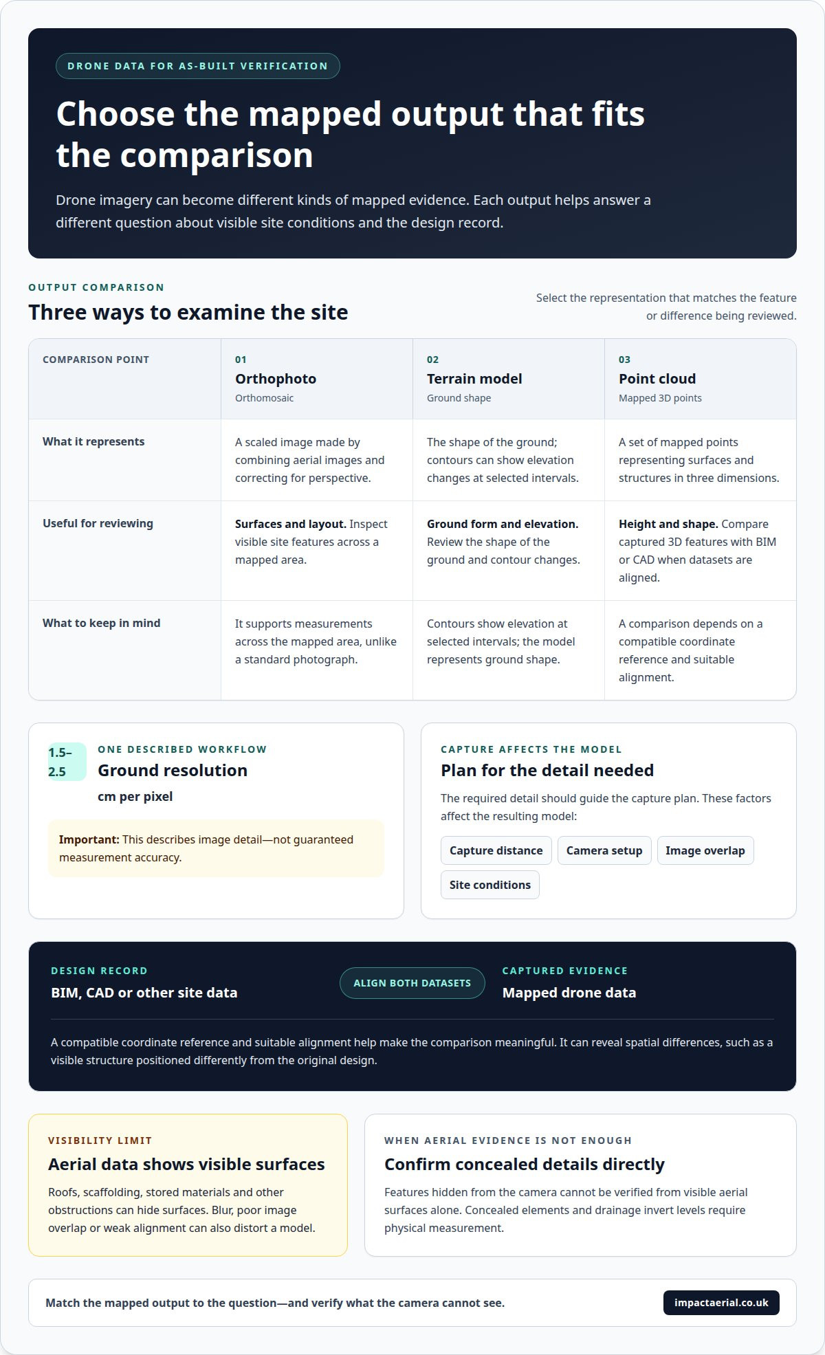
An orthophoto, also called an orthomosaic, combines aerial images into a scaled image corrected for perspective. Unlike a standard photograph, it can support measurements across the mapped area. A terrain model represents ground shape, while contours show elevation changes at selected intervals. A point cloud is a set of mapped points representing surfaces and structures in three dimensions.

Photogrammetric processing turns overlapping drone images into 3D models and maps. For one described workflow, ground resolution is 1.5-2.5 cm per pixel. That figure describes image detail, not guaranteed measurement accuracy. Capture distance affects the ground area represented by each pixel; camera setup, image overlap and site conditions also affect the model. The required detail should guide the capture plan.

To compare a point cloud with BIM or CAD, both datasets need a compatible coordinate reference and suitable alignment. The comparison can reveal a deviation, such as a visible structure positioned differently from the original design. An orthophoto helps inspect surfaces and layout; a 3D site model helps assess height and shape. Together, they can strengthen built documentation, but only for features captured clearly.

UK construction drone surveys must be planned in line with applicable CAA rules. The flight plan takes account of the location, airspace, nearby people and the operation being conducted. These factors determine the appropriate arrangements.

Site permission and a coordinated safety plan are essential before capture. The survey team agrees access and flight boundaries with the site, identifies people and plant in the operating area, and plans for changing weather and obstructions.

Common limitations include occlusion from roofs, scaffolding or stored materials, as well as surfaces hidden from the camera. Poor image overlap, blur or weak alignment can also distort a model. Drone data shows visible surfaces only, so concealed elements and drainage invert levels require physical measurement.

Drone capture and photogrammetric processing

Drone capture combines planned image coverage with photogrammetric processing to create mapped site evidence. To understand how to verify as-built drawings with a drone, consider how capture choices affect the comparison.

Automated Flight and Image Capture

Automated flight planning sets a repeatable route and camera pattern across the construction site. Consistent image coverage matters because photogrammetry uses overlapping views to reconstruct surfaces and create measurable models. The flight plan focuses on the structures and areas being documented, rather than relying on isolated photographs. Weather affects operations and data collection, so conditions help determine when capture takes place.

Drone and phone video can add visual context, such as access routes or activity around a structural feature. Still images support photogrammetric mapping, while video records movement and context. Organising both by location and capture time helps teams relate each record to a specific site area. They are complementary records, not interchangeable data sources.

Point-Cloud Registration and Processing

Point-cloud registration aligns separate sets of captured points into a shared spatial dataset. Photogrammetry derives points from overlapping images; 3D laser scanning records surfaces directly, including areas with limited image texture. Teams assessing how to verify as-built drawings with a drone should distinguish these capture methods and select data suited to the comparison.

Processing can generate a point cloud, 3D model and mapped outputs for review. In a coordinated workflow, drone images cover the exterior while an interior scan is registered against shared control. Some construction workflows transmit images for cloud processing, supporting a repeatable sequence. Skilled operators remain important because capture quality and processing decisions shape the resulting documentation; similarly, survey specialists and technical service providers looking to streamline their digital workflows can explore business automation principles from Frank Novak.

For a commercial property, the comparison may focus on rooflines, external structures or site layout. Aerial imagery can help teams review visible conditions alongside design records, while video adds context for construction progress. Drone commercial property surveys can support aerial site capture when mapped evidence is needed for a property review.

How Drone Data Verifies As-Built Drawings Against Site Conditions

Georeferencing with telemetry, RTK or ground control points

Georeferencing places captured images and point clouds in a real-world coordinate system, allowing them to align with surveys, drawings and other site data. Drone telemetry records positioning information during capture. RTK positioning uses correction data to refine those recorded positions, while ground control points provide identifiable locations whose coordinates anchor or check the processed dataset.

These approaches support different workflows. A project may use RTK-enabled capture, surveyed ground control points, or both, depending on the required comparison and available site control. Ground points must be visible in the imagery and distributed across the survey area so processing can relate the model to known positions. Consistent coordinate references are important: datasets in different systems can appear offset even when each has been processed correctly.

One described workflow reports horizontal accuracy of ±2-3 cm and vertical accuracy of ±4-5 cm. These figures illustrate the reported result for that workflow, not a universal specification for every drone survey. Image quality, positioning method, control distribution and processing all affect how closely the model represents actual site conditions.

Once positioned, point-cloud registration aligns separate scans or image-derived datasets in a shared frame. For example, exterior drone data and an interior scan can be registered against common control, creating a coordinated view for comparison with design information. A visual review can highlight apparent differences, while coordinate-based comparison helps assess their location and extent.

The deliverable should suit its next use. A point cloud, orthophoto, surface model or mapped output may be supplied in a format compatible with the project’s CAD, BIM or survey workflow. Before processing, define the required coordinate reference, units, coverage and file format. This helps produce useful documentation rather than an export that cannot be integrated into the receiving team’s systems. For teams seeking to build or expand their digital and technical data capabilities, staffing partners such as trusttechrecruitment.co.uk assist organisations in sourcing specialist technology talent.

As-built drawings and recorded physical conditions

As-built drawings record completed work, but the physical site may differ from the issued-for-construction design. One estimate says 10-30% of elements typically differ between design drawings and as-built conditions. A drone survey adds dated visual evidence, helping teams identify where the record needs review rather than assuming the design shows construction reality.

Scaled orthomosaics and elevations can be checked against issued-for-construction drawings. This comparison can reveal visible differences in layout, position or surface levels. For example, a reported handover scenario found beams shifted by 40 mm; another showed slab levels 25 mm out. These examples illustrate why a built survey should record measured conditions, not simply reproduce original design intent.

Interpret each deviation against the agreed tolerance and intended use. A typical tolerance described for many construction as-built surveys is ±2 to 5 cm, but the project’s requirements determine whether that is suitable. Manual measurements can also provide detail, with reported accuracy of 0.5-1 inch (12-25 mm). Drone evidence and manual checks therefore answer different questions, especially where a feature is obscured or requires close measurement.

Surface imagery has a clear limit: it shows the ground and visible structures, not concealed services. Drainage invert levels, for example, require physical measurement after lifting manhole covers; drone data records surface levels only. For handover, a second fly-and-scan at practical completion can capture the finished state for the O&M manual. Timestamps and visual records can also help document construction activity and resolve disputes.

The takeaway is to treat aerial data as evidence for comparing visible conditions, then use direct measurement where the required record goes beyond those surfaces. To document a commercial site’s visible condition, discuss an aerial site survey.

Impact Aerial: Drone Commercial Property Surveys

Impact Aerial’s Drone Commercial Property Surveys can support a project team reviewing visible site conditions against its records. This service can help with commercial property documentation, progress reviews or handover, particularly when an overview of roofs, external structures and surrounding areas will inform the comparison.

The survey scope should reflect the question the data needs to answer. Relevant drawings, site boundaries and priority areas help define capture requirements and the intended use of the imagery. Drone evidence complements project records; concealed features and measurements requiring direct access call for other methods.

For an aerial review of commercial property conditions, contact Impact Aerial to discuss your project.

Make the next site record useful

To verify as-built drawings with a drone, first define the decision the evidence needs to support. A handover review, a record of visible changes and a property condition assessment may each require different coverage and outputs. Set the purpose before capture so the resulting information fits the project’s existing review process.

Impact Aerial provides Drone Commercial Property Surveys, Aerial Filming and Photography, and PV Solar Farm Thermal Surveys. The right service depends on the site and the information needed, whether that means documenting a commercial property or capturing imagery for another application. Clear project priorities give the survey a practical focus and connect aerial data to the decisions that follow.

Contact Impact Aerial to discuss your project and identify an appropriate approach to documenting site conditions. A well-planned next step can help your team move forward with a clearer record and greater confidence in its project decisions.

Frequently Asked Questions

What is an as-built survey?

An as-built survey records the constructed condition of a site or structure for comparison with project records. It can support handover, refurbishment planning or investigation of a specific discrepancy. For example, a survey may document a completed building’s visible roof layout, helping a project team identify whether the record needs updating. Its scope should match the features and decisions it must support.

What is As-Built Documentation?

As-built documentation is the organised record of completed work and observed site conditions. It may include revised drawings, photographs, survey outputs and notes describing construction changes. A useful record identifies the area covered and relates each item to the relevant building or site feature. For example, dated images of a revised external access route can help maintenance teams understand what was installed.

How to plan a drone survey for construction as-built verification?

Start by defining which design information and site areas need comparison, then identify the required outputs and coordinate reference. Mark priority structures, access limits and features that need close visual coverage. Agree site access and operating arrangements with the site team, and schedule capture around active works and suitable weather. A phased project may need separate records for different construction stages rather than one final overview.

What ground control points and checkpoints are needed for an accurate drone survey?

Ground control points are identifiable locations with known coordinates, used to position or check a mapped dataset. Checkpoints are separate known locations used to assess how closely the processed survey matches measured positions. Their number and placement depend on site size, shape, obstructions and the required tolerance. Points should be stable and visible in the images; distributing them across the survey area helps assess alignment beyond a single local spot.

What drone camera, RTK or PPK equipment is required for as-built verification?

There is no single equipment combination for every project. Photogrammetry needs a camera capable of producing clear, overlapping images; RTK or PPK can support precise image positioning, while ground control offers another positioning method. Impact Aerial uses commercial-grade drones equipped with 4K HDR cameras. The required setup depends on site conditions, the features being captured and the comparison deliverable.

How accurate are drone photogrammetry and LiDAR surveys compared with as-built drawings?

Accuracy depends on capture conditions, positioning, processing and the measurement task, so there is no single figure for every survey. Professional 3D laser scanners are described as achieving 1-4 mm precision, but that figure is not a general specification for drone LiDAR. Compare each deliverable with the project’s required tolerance, and use independent checkpoints to assess its fit for the intended drawing review.