
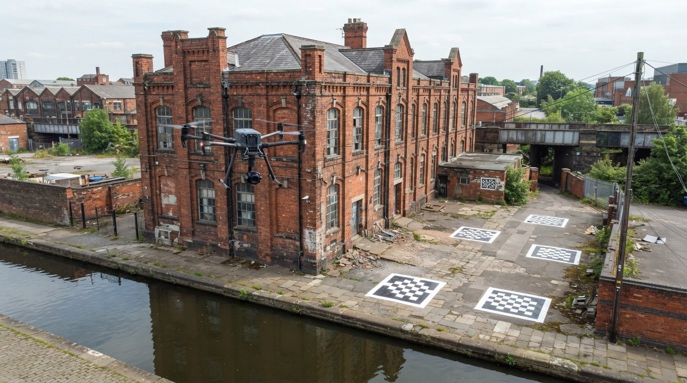
Accurate Revit models start with well-planned drone imagery: traditional photogrammetry typically needs 60-80% overlap between photos. To understand how to create a 3D model from drone photos for Revit, a professional processes the overlapping images into a 3D dataset, builds a triangulated irregular network (TIN) surface where terrain is needed, then selects an export suited to the Revit workflow.
Getting enough overlap matters, but so does capturing the right detail for the intended use. A visually realistic model and a dataset intended for measurement have different priorities, and surfaces such as glass, water or thin vegetation can make reconstruction harder. This guide explains how aerial photogrammetry works, what affects image quality, how photos become a TIN surface, and which outputs can support Revit or other software. You’ll also see what information helps a professional plan the survey and deliver data suited to the project.
Key Takeaways
- Define whether the Revit model needs to look realistic or support reliable measurement, as that choice shapes the capture and processing brief.
- Match the export to its purpose: a textured mesh supports visualisation, while a point cloud is better suited to measurement workflows.
- Understand how image quality and difficult surfaces can affect the TIN, and why removing blurry photos helps improve processing results.
- Set expectations for coordinate reference, units and scale so the delivered data fits the intended Revit workflow.
How professionals capture and process overlapping drone photographs
Professional capture starts with the model’s purpose: visual realism or reliable measurement. That choice guides flight planning, image processing and how the resulting data can support Revit.
Overlapping Photo and Video Capture
Photogrammetry combines overlapping photographs; traditional drone capture typically uses 60-80% overlap. This gives processing software shared visual features to match across images and reconstruct the subject. A traditional survey may use 200-500 or more geotagged photos. For video-based modelling, guidance recommends 4K, an 80-150-foot flight altitude and a 30-45-degree downward camera angle. A full orbit typically takes 60-90 seconds. Video can provide continuous coverage, while 1080p produces a lower-resolution model but processes faster. Professionals use the resulting data as a reference for Revit modelling.
LiDAR and Photogrammetry Processing
Photogrammetry software aligns images, estimates camera positions and reconstructs matching features as a point cloud or textured mesh. Blurry photographs are removed before processing because they can undermine the reconstruction. The selected output then supports the Revit workflow: a technician can use survey data as a reference when modelling terrain or exterior geometry. LiDAR follows a different capture route, recording laser returns to create 3D data, usually as a dense point cloud. It suits geometry-focused work and complex terrain or vegetation, but its heavier files need more specialised processing.
Surveying Rules and Model Accuracy
UK CAA requirements apply to the drone flight, not just to its surveying purpose; capturing survey images doesn’t exempt an operation from applicable rules. Professional flight planning accounts for those requirements and the site’s constraints. Photogrammetry accuracy depends on image quality, overlap, lighting, surface texture and control data. Water, glass, glossy finishes, thin vegetation, inconsistent lighting and blur can make reconstruction harder. Ground control and positioning corrections can help improve a survey’s positional accuracy. One project reported approximately 40 mm global accuracy at ground control point level, an example rather than a universal result.
Choosing export formats for Revit and other software
Choose exports according to the software and task, not simply the file that looks most detailed. A Revit workflow may need visual context, measurable survey data, or both.
Mesh and Point Cloud Formats
A textured mesh represents surfaces and appearance, while a point cloud records spatial points for measurement and reference. Shareable textured meshes commonly use GLB or GLTF, with FBX or OBJ sometimes suitable. Point clouds for engineering workflows can use LAS/LAZ or E57, depending on the workflow. These formats serve different purposes, so the right choice depends on whether the priority is viewing surface detail or working with spatial data.
Before commissioning a model, specify the intended software and task. For example, a textured mesh can show a building’s appearance, while a point cloud can provide geometric reference for measurement. File size and processing requirements also matter, especially with dense datasets. The delivery should explain each file’s purpose and include brief viewing instructions, so the recipient can open the right output without guesswork.
GIS, CAD, and BIM Exports
GIS, CAD and BIM workflows use survey outputs differently, so the export brief should name the destination software and intended use. GIS work may prioritise spatial context; CAD may use survey geometry as a drawing reference; BIM teams may need data aligned with a Revit modelling task. State whether the deliverable is for visualisation, measurement or design coordination, rather than requesting a generic “3D model”.
For measurement deliverables, define units and scale clearly. Also specify the coordinate reference expected by the project, because consistent spatial positioning matters when combining survey data with existing information. The professional preparing the files can then explain which output suits each task and supply viewing instructions. For a commercial property survey, aligning the drone survey outputs with the intended Revit workflow helps the team understand what each file is for.
How professionals process drone photos into a TIN surface
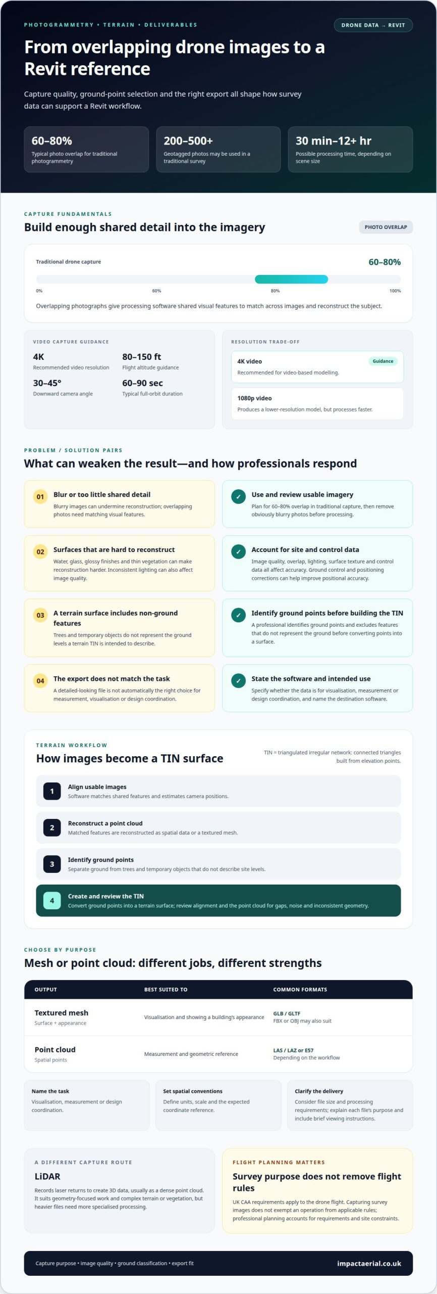
A triangulated irregular network, or TIN, represents terrain as connected triangles built from elevation points. To create one, processing software aligns usable images, reconstructs a point cloud and identifies ground points. A professional then converts those points into a surface, excluding features that do not represent the ground. This distinction matters in Revit: a terrain surface should describe site levels, not trees or temporary objects.
Before processing, professionals remove obviously blurry images, which can weaken reconstruction. They review image alignment and the resulting point cloud for gaps, noise and inconsistent geometry. Processing can take from 30 minutes to more than 12 hours, depending on scene size. Free image or video tools may suit limited viewing or experimentation, but commissioning decisions should focus on the required output, usable controls, processing capacity and delivery formats. Software alone doesn’t make a dataset suitable for measurement or Revit.
Drone video needs a different preparation route from still photographs. A professional selects usable frames from the footage, then processes them to match features and reconstruct geometry. Frames with motion blur, repeated views or changing exposure may provide less useful detail. The resulting mesh or point cloud still needs review for incomplete surfaces and alignment before it can serve as a reliable project reference.
To clean and optimise a drone-generated model for Revit, a professional can remove stray points, isolate the relevant site area and reduce unnecessary mesh detail while preserving important geometry. They also prepare the output for the agreed units, scale and coordinate reference. A site TIN, for example, should retain meaningful level changes rather than smooth them away. The final file is checked for coverage and usability, then saved in a format suited to the Revit workflow, with a brief explanation of its intended use.
Aerial photogrammetry using drones
Aerial photogrammetry turns drone imagery into spatially referenced information for mapping sites and structures. For Revit, the aim isn’t simply a convincing view; it’s data suited to the project’s location and design purpose. One project’s survey outputs used OSGB 1936 (OSTN15), providing a defined coordinate reference for combining survey information with design data. This connection between capture and project coordinates is central to useful reality capture.
Survey capture and Revit modelling are separate stages. In a documented project, the drone survey took one day, including installation of a temporary ground control station and digital data capture. The imagery was processed into digital outputs within 3 days. A Revit technician then spent a further 10 days modelling the survey data. The sequence shows why a survey dataset shouldn’t be confused with a finished BIM model.
That project, led by Walter Lilly from RIBA Stage 0 to Stage 2, used the drone data to create a basic mass-element white model. It represented the site’s topography and exterior in Revit. This is a practical example of aerial photogrammetry informing early design: the survey supplied existing-site context, while the technician turned that information into model elements. The level of detail followed the project’s purpose, rather than aiming to model every visible feature.
For a Revit brief, define whether the priority is site context, exterior form, visualisation or measurement. That decision shapes the required survey data, coordinate reference and modelling scope. It also clarifies which work belongs to photogrammetry and which requires Revit modelling. To discuss aerial data capture for a property project, arrange a drone survey discussion.
Impact Aerial: Drone Commercial Property Surveys
Impact Aerial provides Drone Commercial Property Surveys for teams needing aerial information for property assessment and project planning. If you’re commissioning a survey to inform a Revit workflow, explain the intended use, such as site context, exterior reference or measurement, and specify the required coordinate reference, units and scale. These details help define how the captured information fits the wider project. Revit modelling is separate from aerial data capture.
Impact Aerial operates commercial-grade enterprise drones with 4K HDR cameras and CAA GVC certified pilots. This professional aerial capture can support property projects where site or building information needs to be reviewed from above.
To discuss a Drone Commercial Property Survey for your project, contact Impact Aerial.
Set your Revit project up for its next decision
The most useful model is the one that supports the next project decision, whether that means assessing a site, coordinating design work or planning a property survey. Before commissioning capture, align the intended Revit use with the team responsible for modelling. A clear brief connects the aerial data to the project’s questions, rather than collecting detail without a defined purpose.
For teams considering how to create a 3D model from drone photos for Revit, Impact Aerial’s Drone Commercial Property Surveys can provide aerial information for property projects. Its Aerial Filming and Photography and PV Solar Farm Thermal Surveys serve different project needs, from visual documentation to solar-farm inspection.
Bring your project requirements together and discuss the next step with Impact Aerial. A well-defined brief gives your team a practical starting point.
Frequently Asked Questions
How do professionals create great 3D drone scans?
Professionals plan the capture around the feature the model must represent, such as a roof, façade or site boundary. A clear brief establishes how to create a 3D model from drone photos for Revit, including which surfaces and details matter. They then assess the reconstructed result for gaps and distortions. A roof model, for example, needs clear coverage of roof planes and edges.
What is photogrammetry?
Photogrammetry derives measurements or three-dimensional information from photographs. Software identifies features appearing across multiple images and uses their changing positions to estimate shape and spatial relationships. For a building, overlapping views can help reconstruct roof and façade geometry. The result may be a point cloud or textured mesh, which can inform a separate modelling workflow.
Which formats can a provider use to export your drone 3D models?
Common options include GLB or GLTF for shareable textured meshes, with FBX or OBJ also used in some workflows. Engineering point clouds can be supplied as LAS/LAZ or E57. For example, a team reviewing surface appearance may need a mesh, while a team measuring geometry may need a point cloud. Agree the intended software and use before choosing the deliverable.
What drone photos should you provide for accurate 3D modelling?
Provide original, clear photographs covering the subject from multiple viewpoints, along with geotagged image data where available. Include the project boundary and identify the surfaces or features the model needs to represent, such as a building exterior or terrain. Avoid relying on images with blur or inconsistent lighting. Glass, water and glossy surfaces can also make reconstruction more difficult.
How much image overlap should you request for drone photogrammetry?
Traditional drone photogrammetry typically uses 60-80% image overlap. This gives processing software shared visual details to match between photographs and helps reconstruct the subject. The suitable capture plan also depends on the scene and the intended model. A provider can use the project brief to plan coverage, especially where complex geometry or difficult surfaces may limit usable image detail.
Which photogrammetry software can a provider use to create 3D models from drone photos?
The software choice affects how to create a 3D model from drone photos for Revit, because processing must suit the capture data and required output. Photogrammetry software aligns photographs, reconstructs spatial data and generates deliverables such as a textured mesh or point cloud. Ask for the output formats and viewing instructions in the handover. Image or video editing tools aren’t substitutes for photogrammetry processing.
 2 Norton Drive, Wythall, Birmingham, B47 6HH Company registration number: 11138586. VAT Number: 366 9068 55


