
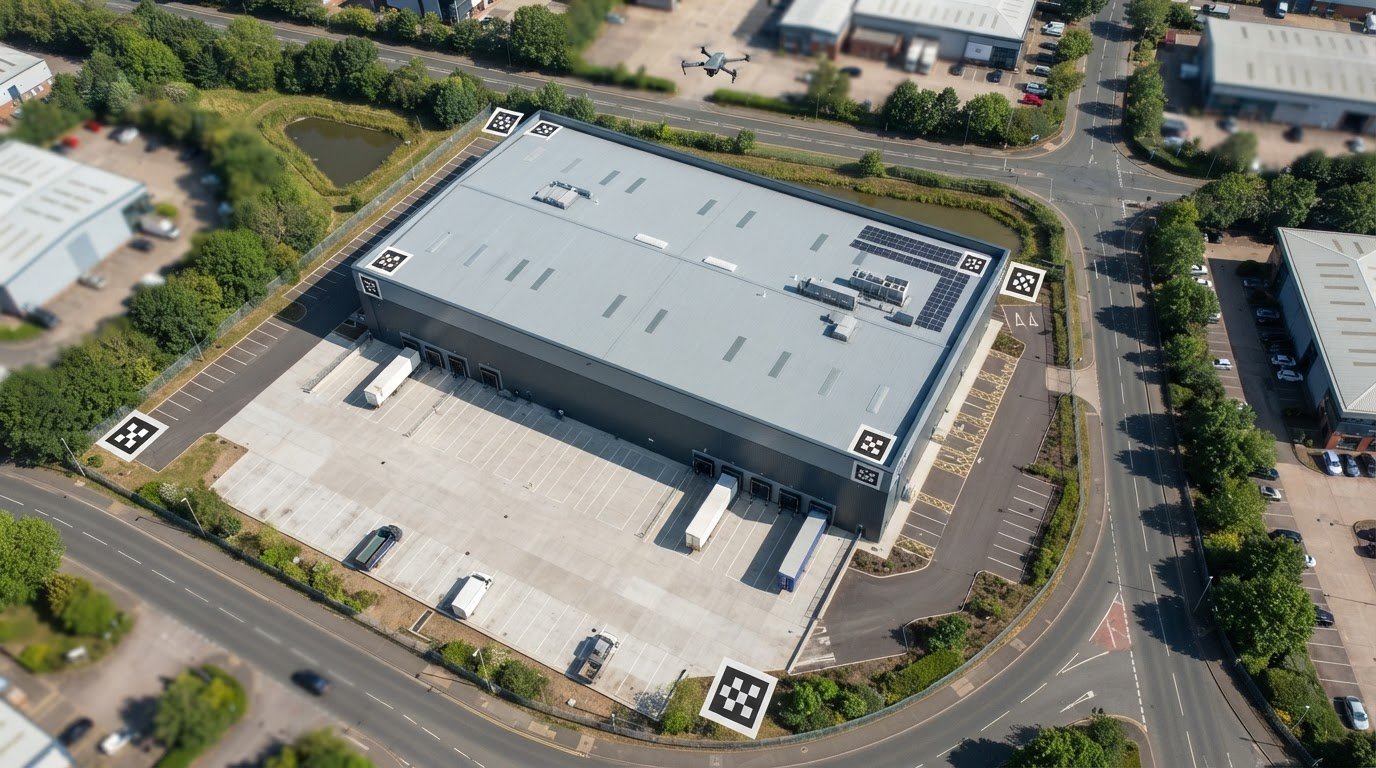
A drone image isn’t usable AutoCAD linework until it’s processed, referenced and converted into the right CAD format. To understand how to export drone data to AutoCAD, a professional first plans the capture around the required output, processes the imagery into a photogrammetric product, then uses ground control and CAD alignment to prepare vector linework, often as a DXF.
It’s understandable to expect a direct export from the drone, but the quality of the drawing depends on the steps between capture and CAD. The imagery may also produce a georeferenced GeoTIFF, elevation data, a point cloud or a 3D mesh, depending on the project. This article explains how those outputs are created, how imagery and ground control inform AutoCAD linework, and why a raster may need adjustment to align with a DXF in AutoCAD. You’ll also learn what affects the result and when professional processing can make the handover more reliable.
Key Takeaways
- Define the intended CAD deliverable before capture, since the required output shapes the flight plan and image collection.
- Understand how one imagery dataset can support different mapping and modelling outputs, from orthomosaics to point clouds and meshes.
- See how ground control, georeferencing and careful raster alignment affect the accuracy of CAD linework.
- Follow the professional workflow from image processing through export and final checks, so the handover suits the project’s needs.
Photogrammetric data for mapping and modelling software
For UK land, construction and boundary work, agree the intended use, coordinate reference system and accuracy requirements with the project surveyor. Drone imagery records visible conditions, but a traced line alone does not establish a legal boundary.
- Choose the required surface model. A digital terrain model represents the ground surface, while a digital surface model includes visible features such as roofs and vegetation. On a construction site, a terrain model may support ground assessment; a surface model can show structures and other raised features. Specify the measurements needed before processing.
- Request an orthophoto for plan-based work. An orthophoto corrects image perspective to create a consistent aerial view for mapping. A georeferenced GeoTIFF preserves scale and spatial reference information, making it useful for site and land surveys, roof plans and elevation drawings. That information helps place the image within a mapping workflow.
- Match the output to the task. Use an orthophoto as a visual base for tracing visible features, such as roof edges or access routes. Use a terrain or surface model when the task depends on elevation. Measurements from any output depend on processing, ground control and alignment, so let the project specification determine which measurements are suitable.
- Organise 3D models and project layers. A photogrammetric model adds depth to the mapped site, helping teams inspect building form and existing conditions. Keep the orthophoto, elevation models, point cloud and CAD linework as distinct, clearly named layers or files. During upload into mapping or modelling software, retain coordinate information and record each output’s purpose for later review.
For 2D CAD outputs, capture should prioritise consistent nadir or façade imagery, proper overlap for 2D processing, and accurate scaling and georeferencing. Set the capture plan around the drawing purpose, and keep the selected view consistent across the area being documented. Confirm that overlap is suitable for the intended 2D processing, and carry the scale and georeferencing requirements through to the output. These priorities help align the CAD deliverable with the imagery, rather than treating image capture and drawing preparation as separate decisions. Record the capture choices with the project outputs so they can be reviewed alongside the resulting linework.
Processing imagery into orthomosaics, elevation mosaics, point clouds and meshes
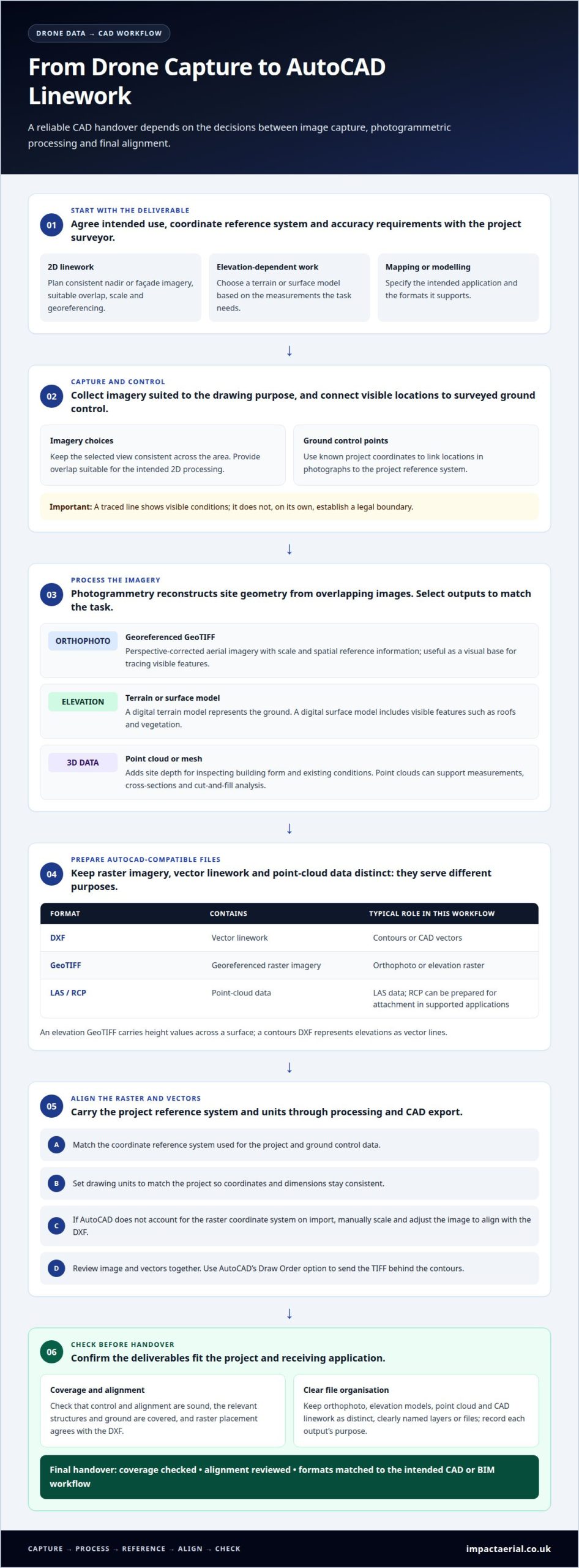
- Select the processing workflow and deliverables. Photogrammetry software reconstructs site geometry from overlapping images, producing orthomosaics, elevation mosaics, point clouds or meshes. Outputs should match the task, with coverage and alignment checked before export. Mapping platforms can create AutoCAD-compatible DXF vectors and GeoTIFF imagery, which serve different purposes: DXF contains linework, GeoTIFF contains georeferenced raster imagery, and LAS contains point-cloud data.
- Prepare raster and contour outputs for CAD. An elevation GeoTIFF represents height values across a surface; a contours DXF represents those elevations as vector lines. AutoCAD may not account for a raster’s coordinate system when importing it, so scale and adjust the image manually to align with the DXF. Review the image and vectors together, then send the TIFF behind the contours using AutoCAD’s Draw Order option.
- Package point clouds for the receiving application. LAS files support drone-generated point clouds and 3D modelling workflows. Providers can prepare an RCP point cloud for attachment in AutoCAD, Revit or Civil 3D, subject to the receiving application’s supported formats. In AutoCAD, an RCP file is attached from the Insert tab’s Point Cloud section. Civil 3D or another product isn’t automatically required; the deciding factor is whether the chosen application supports the delivered format and intended workflow.
- Use the cloud to analyse existing conditions. A classified point cloud can support distance and volume measurements, cross-sections, cut-and-fill analysis and existing-condition models. Design teams can also compare proposed design intent with captured site conditions. Before delivery, check that the cloud covers the relevant structures and ground.
- Resolve alignment and export issues before handover. Coordinate mismatches, incomplete coverage or unsuitable formats can disrupt CAD use. The provider checks control and alignment, then corrects raster placement against the DXF. For commercial property survey data, specify the intended CAD or BIM workflow so deliverables match the project.
Converting drone imagery and ground control data into AutoCAD linework
- Set the project coordinate reference system and units. Understanding how to export drone data to AutoCAD starts with matching the project coordinate reference system to the ground control data. Apply the same reference during photogrammetric processing and CAD export. Drawing units must also match the project, such as metres for site measurements, so coordinates and dimensions stay consistent.
- Connect imagery to surveyed ground control. Ground control points link visible locations in drone photographs to known project coordinates. Incorporate them during processing, then assess how well the resulting model fits those points. Required accuracy depends on the survey’s intended use and deliverable; a single accuracy figure does not suit every AutoCAD project.
- Prepare and align the georeferenced image. Process the photographs into an orthophoto, then export a georeferenced GeoTIFF when a raster base is needed. AutoCAD may not account for the raster’s coordinate system on import, so scale and adjust it manually against the DXF linework. Project references and control points guide the alignment.
- Trace relevant features as CAD vectors. Use the aligned image as a visual reference to digitise agreed details, such as roof outlines, visible site edges or access routes, into a DXF. Named layers help CAD users distinguish features. A sound process for how to export drone data to AutoCAD also distinguishes visible image features from legal boundary determinations: tracing alone does not establish a boundary.
- Check the drawing against its source data. Overlay the DXF with the orthophoto and review control-point fit, units, coordinate placement and gaps. In AutoCAD, selecting a contour line displays its assigned Elevation in Properties. Before saving or handing over the drawing, check that the linework represents the agreed features.
A georeferenced GeoTIFF provides a raster image base, while a DXF contains digitised CAD vectors on named layers.
Drone imagery can be processed into 2D maps or 3D models, and one dataset may be used to generate both outputs. In a project that needs CAD linework, these options provide different ways to represent the same captured material. The choice between them can be made alongside the intended form of the final project output.
Export Drone Survey Data to AutoCAD Step-by-Step
- Confirm the CAD deliverable. Confirm which features and outputs the project needs before exporting. A site plan may require DXF linework and a georeferenced GeoTIFF, while a modelling workflow may need a point cloud. Use the agreed coordinate reference system and drawing units to guide processing and export settings.
- Process the imagery. Photogrammetry software aligns the photographs and ground control data to create the selected outputs. The professional reviews image coverage, model alignment and visible gaps before preparing CAD files. Where both a raster and vectors are required, the orthomosaic and linework need consistent spatial referencing.
- Digitise the requested features. The professional traces agreed details, such as roof edges, site boundaries visible in imagery, or access routes, into vector linework. Features are organised into named layers so CAD users can distinguish them from each other. A DXF is suitable when the handover requires editable 2D vectors.
- Export and align the raster. Export the GeoTIFF with georeferencing for use as an image base. AutoCAD may not account for the raster’s coordinate system on import, so scale and adjust it manually against the DXF. Then send the TIFF behind the linework using AutoCAD’s Draw Order option.
- Check elevations and point-cloud files. For contour deliverables, check that line elevations correspond with the processed surface. In AutoCAD, select a contour and read Elevation in Properties to see its assigned height. If a point cloud is required, attach the RCP file from the Insert tab’s Point Cloud section.
- Review and save the drawing. The professional checks the layers, coordinate placement, raster alignment and requested features, then saves the drawing as a DWG using File > Save As > Drawing. For professional drone survey processing, provide the intended CAD outputs and project reference system at the outset.
Impact Aerial: Drone Commercial Property Surveys
Impact Aerial provides Drone Commercial Property Surveys for property teams that need a clear aerial view of buildings and site conditions. A professional survey can document roof details, external features or a wider property overview for project planning. Define the relevant areas and features, and whether the information will support mapping, modelling or a CAD workflow. That context helps shape the capture and determine which outputs will be useful. For commercial building projects, an aerial survey can help turn imagery into information for property work, rather than leaving it as standalone photographs.
If a commercial property survey is relevant to your project, contact Impact Aerial to discuss your requirements.
Plan Your Next Survey with Confidence
Start by defining the decisions the finished drawing needs to support. A facilities team may need a consistent record for planned maintenance, while a project team may need information that fits its design workflow. A clear purpose gives the survey a focused brief and helps keep the handover relevant to the people who will use it.
Understanding how to export drone data to AutoCAD is only part of planning a successful project. The deliverable also needs to suit its intended use, the receiving team and the wider project process. Discussing requirements at the outset helps establish a practical direction for the work.
Discuss your project with Impact Aerial and take the next step towards drone data that supports your plans.
 2 Norton Drive, Wythall, Birmingham, B47 6HH Company registration number: 11138586. VAT Number: 366 9068 55


